
Contact
Write to Us And We Would Be Happy to Advise You.
Do you have any questions, or would you like to speak directly with a representative?
By ren
How to expand a PCB prototype hole? The printed circuit board (PCB) is the building block of electronic equipment, and it may be found in almost every electronic device in use today. The complexity and excellent performance of PCBs are determined by the diversity of high-tech items. Perf
board material used for manufacturing electrical circuitry.
We all know that the majority of scientific breakthroughs are the product of several trials. Before a new product goes into mass production, a PCB prototype is required. On the one hand, the PCB prototype allows design flaws to be fixed and building circuits design performance to be enhanced at a cheap cost and in a short amount of time. On the other hand, it aids in the prevention of further difficulties and the reduction of hazards in mass manufacturing.
• When it comes to PCB prototypes, consumers prioritize speedy turnaround when selecting a manufacturer. If you're an engineer, a student, or a hobbyist, you want to know as quickly as possible whether your design has produced the intended impact. Furthermore, the sooner you get the prototype PCB, the sooner you can test it and begin mass production.
• Second, all business people, particularly students, are concerned about costs. A finished product may need several PCB prototype iterations. When developing a PCB prototype, the goal is to keep costs low.
• Quality assurance of good performance and dependability is the third element. Customers care most about quality, even if quickness and cheap cost are important to them. Yes, regardless of the price, you do not want to buy a low-quality, dangerous PCB.
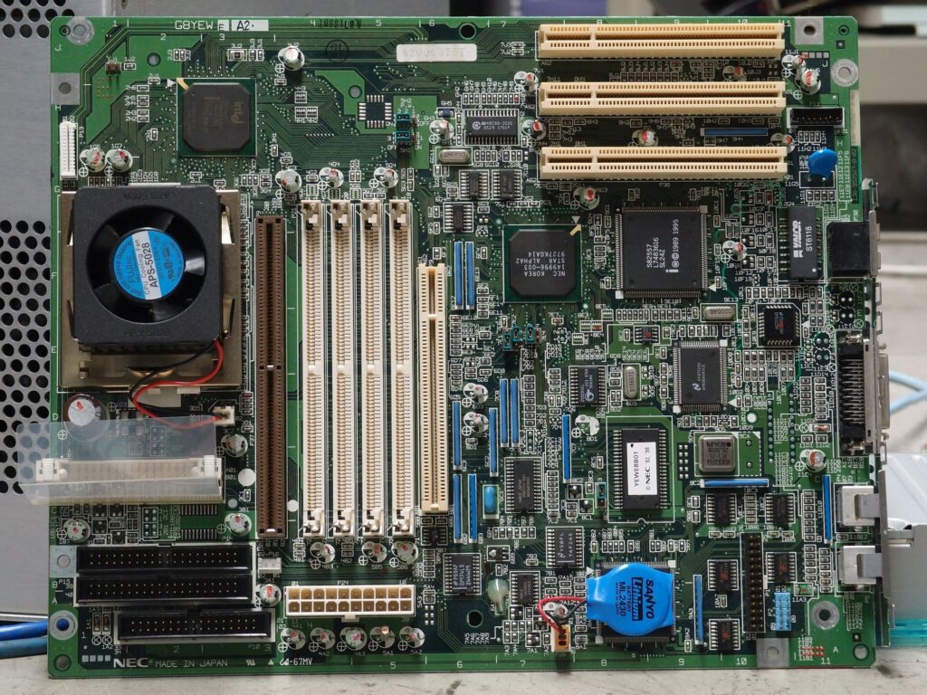
Through-hole technology (also spelt "thru-hole") refers to an electronic component mounting scheme in which leads on the component are inserted into holes drilled in printed circuit boards (PCBs) and solder mask to pads on the opposite side instead of the same side, either manually (hand placement) or using automated insertion mount machines.
When PCB prototyping, design engineers frequently favour bigger through-hole components than surface mount parts because they are easier to utilize with breadboard sockets. High-speed or high-frequency designs, on the other hand, may need SMT technology to reduce stray inductance and capacitance in wire leads, which would degrade circuit performance. Even in the prototype phase, ultra-compact designs may need SMT fabrication.
You'll need the correct equipment to drill PCB hole sizes. PCB drills are available to assist you with your task. They come in a variety of sizes, beginning at 0.05mm, and may be used to drill a variety of holes, including Via holes. Before plating, holes are usually drilled.
Every PCB has these holes. They aid in the connection of the PCB to the GND plane. The concept is that the hardware cannot be glued onto a PCB. Vias may be added to the supported mounting in certain circumstances to assist supply adequate ground connections. It also aids in the support of the PCB when the nut is tightened with excessive torque. It's important to know that, in addition to employing PCB mounting holes to secure your PCB enclosure, they may also be utilized to prevent electromagnetic interference. The process is known as (EMI) reduction. This implies that PCBs that are EMI sensitive should be housed in a metal enclosure. After that, the plated PCB should be put in holes and grounded. It aids in the grounding of electrical interference.
Although it looks to be a straightforward operation, there are certain guidelines to follow when drilling the holes. It's vital to pay attention to the mounting hole coordinates since making errors diminishes the odds of the PCB being installed correctly in its enclosure. PCB holes that are properly constructed enable you to install your PCBs in their enclosure.
A PCB hole chart gives you basic information about the holes and may help you place components on your board.
Making the holes for the components to be mounted through is always a challenge. As a result, the tolerance and size of the holes must be specified. PCB diagrams are crucial in this case. They provide the hole size to guarantee that your PCB is properly plated. They also provide the software required to add holes to your PCB.
PCB holes were formerly drilled using less sophisticated drills. Before pulling the lever to drill holes, the operators had to arrange the panels on X and Y coordinates in most circumstances. The operation was repeated until all of the holes had been drilled. However, things have changed in recent years, and since a PCB might have up to 1000 holes punched, the previous approach will not ensure that you will drill enough holes. Drilling holes with conventional PCB drills has gotten much simpler. They drill typical PCBs using automated drilling equipment.
Drilling holes without following the recommendations might result in holes that are either too large or too tiny. To begin drilling the holes, you must first get standard bits. Because bits come in various sizes, you may need to specify the hole size you desire.
How to expand a PCB prototype hole? If you can follow the procedures below, calculating PCB hole size is not difficult:
To establish the form and kinds of holes that need to be drilled, first calculate the maximum diameter of the electronic components. Round holes are advised when using round PTH lead, whereas square holes are recommended when using square PTH lead. Rectangle holes may be appropriate for people who will be utilizing rectangle PTH lead.
Depending on the degree of IPC, the minimum size will be computed by looking at the maximum Lead Diameter +0.25mm, 0.20mm, or 0.15 mm.
The size of the annular ring is the next item you should know. For level A, it should be 0.05mm, and for level B, it should be 0.5mm. It should be 0.4 mm for level C. The Pad Diameter should be equal to the minimum house size plus the minimum fabrication allowance plus the minimum annular ring.
The density levels are represented by levels A, B, and C. Level A is appropriate for low one component density, while Level B is appropriate for moderate Design reproducibility. For reflow, drag, dip, or wave soldering, level B is usually chosen. When working with high-density components, however, Density level C is suggested. It is suitable for usage in portable and handheld devices.
Calculation of hole diameter is crucial while answering How to expand a PCB prototype hole? When estimating the PCB hole diameter, the aspect ratio of the hole diameter to the board thickness is usually taken into account. The hole size should be about 0.40mm if the thickness is 1.60mm. This indicates the aspect ratio is 1:4 in this example. If you lower the thickness of your PCB design =, you should likewise reduce this ratio.
How to expand a PCB prototype hole? A hole diameter, or PhD, is the diameter of a manufacturing tool used to drill holes. As a result, the calculations for non-plated through-hole parts and plated through holes varied. The sum of the completed hole size and +0.00mm/0mil is used to calculate a non-plated through-hole. On the other hand, plated through-hole is the sum of the completed hole size plus +0.10mm/4mil.
The PhD computation is as follows:
1. Non-Plated Holes: 1. Finished hole size + 0.00mm/0mil
2. For Plated Through Holes, add 0.10mm/4mil to the finished hole size.
3. PhDPHD – final hole size = applied finish + copper hole plating finish.
Resistors, transistors, and other electronic parts are built into integrated circircuitC) using many layers of semiconductors, copper, and other related materials. Die stands to the cut as well as a formed combination of these wafers.
Intricate connections between layers of semiconductor wafers make the ICs vulnerable. An electrical circuit design may be prototyped using perf boards (also called DOT PCB). Hole spacing is typically 0.01 inch (2.54 mm) on either a square or rectangular pre-drilled sheet of this kind.
Controlling rusting is electrically isolated. Stray current from metals that are not the same can cause corrosion in conductors.
The outer layer annular ring is known as the OAR. You can figure it out by multiplying the difference between copper pad diameter and tool size by two.
The Finished Annular Ring is the piece that fills the space between the solder hole and the rim of the solder pad on the exterior of the component. In addition to this, the annular ring will crack if the hole being drilled is not perfectly centred. However, everything hinges on the comparison of the outside diameter of the solder pad to the diameter of the stipulated hole size.
Read more: How to cut a slot in a PCB prototype board?
Because they are through holes that are drilled at conventional intervals on the circuit board, the tool holes on the circuit board seem to be pretty typical. We won't be able to appreciate their importance until we first examine their jobs in great detail. Some of these through-holes are used to attach hardware to the circuit board, while others are used to assist in the manufacturing and assembly of the circuit board.
Do you have any questions, or would you like to speak directly with a representative?