
Contact
Write to Us And We Would Be Happy to Advise You.
Do you have any questions, or would you like to speak directly with a representative?
By hqt
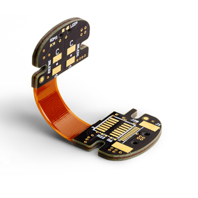
HDI rigid-flex PCBs are gaining popularity in a variety of industries due to their unique ability to combine the best attributes of both rigid and flexible PCBs. HDI rigid-flex PCBs have four layers: a dielectric layer, a conductive layer, a copper foil layer, and a coverlayer. The dielectric layer provides insulation between the conductive and copper foil layers, while the conductive layer provides a pathway for electrical current. The copper foil layer provides structural support and conductivity, while the coverlayer protects the other layers from environmental damage.
The 4 layers HDI rigid-flex PCB is a type of printed circuit board that has four conductive layers. The four layers are made of different materials, which are laminated together. The four layers are then bonded together using an adhesive. The four layers are then etched to create the desired circuit patterns. The four layers are then plated with a thin layer of copper. The copper is then covered with a soldermask and the entire assembly is then covered with an overcoat.
Design Guidelines
PCB design guidelines for 4 layers HDI rigid-flex PCBs are as follows:
There are four main types of HDI rigid-flex PCBs: single-sided, double-sided, multi-layer, and build-up. Single-sided HDI rigid-flex PCBs have only one layer of conductive material. Double-sided HDI rigid-flex PCBs have two layers of conductive material. Multi-layer HDI rigid-flex PCBs have three or more layers of conductive material. Build-up HDI rigid-flex PCBs have a layer of conductive material sandwiched between two layers of non-conductive material.
Single-sided HDI rigid-flex PCBs are the simplest and most cost-effective type of HDI rigid-flex PCB. Double-sided HDI rigid-flex PCBs are more complex and more expensive than single-sided HDI rigid-flex PCBs. Multi-layer HDI rigid-flex PCBs are the most complex and most expensive type of HDI rigid-flex PCB. Build-up HDI rigid-flex PCBs are the second most complex and second most expensive type of HDI rigid-flex PCB.
HDI rigid-flex technology is an ideal solution for space-constrained and/or highly mobile applications requiring the utmost in reliability. HDI rigid-flexible printed circuit boards (PCBs) offer a wide range of benefits over traditional rigid or flexible PCBs, making them the perfect choice for use in a variety of industries.
HDI rigid-flex PCBs are constructed with a thin layer of dielectric material between two conductive layers. This dielectric layer is typically made of polyimide or other high-temperature resins, which allows for the HDI rigid-flex PCB to be bent or flexed without damaging the circuitry.
The thin dielectric layer also allows for HDI rigid-flex PCBs to be significantly thinner than traditional rigid PCBs, which is ideal for space-constrained applications. In addition, the dielectric layer provides excellent electrical insulation, ensuring that HDI rigid-flex PCBs can operate reliably in even the most demanding environments.
HDI rigid-flex PCBs are also much more resistant to mechanical stress and vibration than traditional PCBs, making them an ideal choice for use in mobile or handheld applications. The combination of thinness, flexibility, and durability makes HDI rigid-flex PCBs an ideal solution for a wide variety of applications.
Flexible printed circuit boards (PCBs) are a type of PCB that is built using flexible instead of rigid material. They are used in a variety of applications where flexibility, weight, and space saving are important considerations.
Flexible PCBs are made by bonding a thin layer of conductive material, such as copper, to a flexible substrate. The substrate can be made from a variety of materials, including plastic, paper, and fabric.
Flexible PCBs are used in a variety of electronic devices, including cell phones, laptops, and digital cameras. They are also used in medical devices and industrial applications.
Flexible PCBs offer a number of advantages over traditional rigid PCBs. They are lighter and more flexible, which makes them ideal for applications where weight and space are important considerations. They are also more resistant to shock and vibration, which makes them ideal for applications where reliability is important.
While flexible PCBs offer many advantages, they also have some disadvantages. They are more expensive than rigid PCBs, and they are more difficult to manufacture.
Rigid Printed Circuit Boards (PCBs) are one of the most common types of PCBs used in a variety of applications. They are made up of a substrate material, typically FR-4, and have copper conductors on one or both sides of the board. The copper conductors are typically etch to create the desired circuit pattern.
Rigid PCBs are used in a variety of applications including computer and office equipment, automotive electronics, and industrial control systems. They are also used in consumer electronics such as cell phones, digital cameras, and personal computers.
Rigid PCBs offer a number of advantages over other types of PCBs. They are very reliable and have a long lifespan. They are also less likely to be damaged by shock and vibration.
Rigid PCBs are available in a variety of sizes and thicknesses. They can be customized to meet the specific needs of the application.
While HDI rigid-flex PCBs are typically more expensive than their all-flexible or all-rigid counterparts, the extra cost is often worth it given the advantages they offer. Here’s a look at the PCB assembly process for 4-layer HDI rigid-flex boards.
As with any multilayer PCB, the assembly process for an HDI rigid-flex board begins with the preparation of the inner layers. The inner layers are then laminated together and the outer layers are added. Once the layers have been laminated, the build-up process begins.
The build-up process for an HDI rigid-flex board is similar to that of a standard multilayer PCB. First, the conductive traces are laid down on the inner layers. Next, the vias are drilled and filled. Finally, the solder mask and surface finish are applied.
Once the build-up process is complete, the HDI rigid-flex board is ready for assembly. The assembly process for an HDI rigid-flex board is similar to that of a standard multilayer PCB, with a few key differences.
First, the HDI rigid-flex board must be populated with components. This is typically done using a pick-and-place machine. Next, the board is reflowed to solder the components in place. Finally, the board is inspected and tested to ensure that it meets all specifications.
The assembly process for an HDI rigid-flex board is similar to that of a standard multilayer PCB, with a few key differences. First, the HDI rigid-flex board must be populated with components. This is typically done using a pick-and-place machine. Next, the board is reflowed to solder the components in place. Finally, the board is inspected and tested to ensure that it meets all specifications.
The soldering process is a key step in the production of 4 layers HDI rigid-flex PCBs. It is important to ensure that the soldering process is carried out correctly in order to avoid any issues with the final product. There are a number of factors that need to be considered when carrying out the soldering process, such as the type of solder used, the temperature of the soldering iron, the amount of time the solder is in contact with the metal, and the type of metal being soldered.
As technology advances, the demand for smaller, more efficient electronics increases. This has led to the development of HDI rigid-flex PCBs. HDI rigid-flex PCBs are made up of four layers: a core, two build-up layers, and a flex layer. The core is made up of a dielectric material, such as FR4, and the build-up layers are made up of copper. The flex layer is made up of a flexible dielectric material, such as polyimide.
HDI rigid-flex PCBs are used in a variety of applications, such as mobile phones, laptops, and wearable devices. They offer a number of advantages over traditional PCBs, such as improved flexibility, improved signal integrity, and reduced size and weight.
HDI rigid-flex PCBs are more expensive than traditional PCBs, but the benefits they offer can justify the cost. When choosing an HDI rigid-flex PCB, it is important to consider the specific needs of your application.
PCB mounting is the process of attaching a printed circuit board (PCB) to a device or system. This can be done using various methods, such as screws, bolts, or soldering. PCB mounting is a critical step in the manufacturing process of many electronic devices, as it ensures a reliable connection between the PCB and the device.
There are many factors to consider when choosing a PCB mounting method, such as the type of PCB, the device it will be mounted to, and the environment in which the device will be used.
Do you have any questions, or would you like to speak directly with a representative?