
Contact
Write to Us And We Would Be Happy to Advise You.
Do you have any questions, or would you like to speak directly with a representative?
By ren
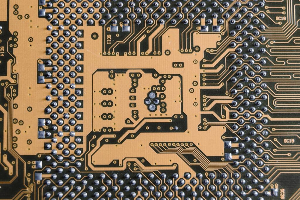
SMT assembly for the Automotive, Surface-mount technology (SMT) is a technique of directly mounting electrical components onto the surface of a printed circuit board (PCB). A surface-mount device is an electrical component that is installed in this way (SMD).
In terms of performance and efficiency for electronics goods, PCB manufacturers report SMT (Surface Mount Technique) assembly has emerged as a leading electronics manufacturing technology.
The SMT assembly technique consists of several phases, each of which adds to the final product's quality. Furthermore, any changes to any production phase may result in a significant cost variance. As a result, having a thorough grasp of the SMT assembly for the automotive industry technique is quite beneficial, as it is also a shortcut to cost reduction without sacrificing performance.
Solder paste printing, solder paste inspection (SPI), chip mounting, visual inspection, reflow soldering, AOI, visual inspection, and ICT (In-Circuit Test), function test, depanelization, and other procedures are included in the SMT assembly technique. Furthermore, having a thorough grasp of the whole method allows you to save manufacturing expenses.
SMT Assembly Procedure Surface mount assembly (SMT assembly for the automotive is a form of the surface mounting component with no or short leads (referred to as SMC/SMD) that is soldered and assembled by reflow soldering or dip soldering on the surface of a printed circuit board (PCB) or the surface of other substrates.
Solder paste printing, which tries to deposit an appropriate quantity of solder paste onto a pad on which components will be soldered, is the first step in SMT assembly for the automotive Three factors influence the quality of solder paste printing: solder paste condition, scraping angle and scraping speed.
Completed PCBs will never be of high quality unless solder paste is properly kept and applied. Solder paste must be maintained at a low temperature in a refrigerator and then returned to room temperature before being used on the SMT production line. Furthermore, the exposed solder paste must be consumed within two hours. Aside from solder paste condition, solder paste printer settings, particularly scrape angle and speed, should be appropriately adjusted, since both are strongly connected to the exact quantity left on the pad.
Solder paste inspection is an optional cost-cutting measure since it is preferable to decrease solder flaws now rather than later. SPI is not a required step in the SMT assembly technique, but it may help you reduce PCB manufacturing costs and enhance product quality. After all, the majority of flaws in SMT assembly are caused by solder paste printing, and if they can be identified and addressed early on, the risks of defects in subsequent stages of production are reduced or even avoided. SPI machine features two types: 2D and 3D. PCB Cart has a 3D SPI machine in the workhouse to give clients with superior inspection PCB assembly services.
Chip mounting plays a core role in the SMT assembly process. This is done by chip mounters, which vary largely in speed and mounting capabilities. Some small components are normally placed by high-speed chip mounters that are capable of placing them quickly to make those components quickly adhere to the solder paste on the pad.
However, big components such as BGAs, ICs, connectors, etc. are often installed by multi-function chip mounters that operate at a modest pace. Alignment is important when it comes to those components. It takes more time to achieve alignment before chip mounting, which is why the speed of a multi-function chip mounter is much lower than that of a high-speed chip mounter. Moreover, some of the components used in multi-function chip mounter don’t rely on tape on the reel while some on tray or tube due to the limitations of size.
After chip mounting, it’s necessary to carry out a visual inspection so that reflow soldering can be largely ensured to be without defects. The leading issues to be found in this step include misplacement, missing parts, etc. Because the faults are permanently bonded into the PCB after reflow soldering, they are exceedingly difficult to deal with. As a result, products’ reliability will go down and production costs will rise as well.
Some components, on the other hand, may be put directly by hand in this stage, such as big components, DIP components, or those that cannot be placed using a chip mounter for various reasons.
Reflow soldering involves melting solder paste to create IMC (Intermetallic Compound) to link component pins to the board. Preheating, temperature increase, reflow, and cooling are all covered by the temperature profile used in the reflow soldering process. Take, for example, lead-free solder paste SAC305, which has a melting point of roughly 217°C and cannot be remelted unless the temperature of the reflow soldering oven is greater than 217°C. Furthermore, the maximum temperature of a reflow soldering oven should not exceed 250°C, otherwise many components will not melt owing to their inability to endure such a high temperature.
The temperature profile selection impacts the quality of reflow soldering and helps to save manufacturing costs. As a result, it is preferable to select an experienced SMT assembler as a CM (Contract Manufacturer) who is well-versed in the factors impacting SMT soldering quality and improvement strategies. All of these factors will result in lower manufacturing costs.
Up to now, components have been fixed onto PCB after reflow soldering, which means that the essential part of the task concerning SMT assembly has been completed. However, the assembled boards can never be directly used in final products unless sufficient tests and inspections have been made. Performance of solder joints can be inspected through the application of AOI that is capable of exposing some defects like a tombstone, edge-on, missing components, displacement, orientation, bridging, empty solder, etc.
X-ray inspection is a complement to AOI since it may detect certain faults more clearly and immediately. It’s not a must-be measure after reflow soldering. However, as long as the SMT assembler cares more about products’ quality and reliability, X-ray inspection machines will be applied to meet the rigorous demands of some OEMs for the achievement of higher efficiency.
By measuring resistance, capacitance, and inductance, ICT attempts to assess if there are any open or short circuits in the electronic circuits and to uncover any component faults. As a consequence, following reflow soldering, components are checked to assure they’re good performance.
ICT only tests openings and shorts on bare boards, not PCB functionality. As a result, function testing should be performed on constructed PCBs to preserve the high dependability of final devices.
Read more: How can hardware start-ups test their PCB Prototypes?
Surface mount technique has various benefits that should impact your rigid flex PCB design. However, there are times when through-hole technology is critical; thus, never lose sight of this. SMT is the best automotive PCB assembly.
Do you have any questions, or would you like to speak directly with a representative?